

The CCD 401
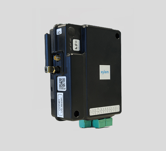 CCD 401 is a wireless modem that is used in pumping stations. The unit is designed to be used with Xylem cloud services only and not as a stand-alone modem.
The unit has a built-in embedded subscriber identity module (eSIM) to send data over the Long Term Evolution (LTE) network. If an LTE network is not available, the unit sends data over a 2G or 3G network. The built-in eSIM provides cellular connectivity through a private Access Point Name (APN).
The Xylem Vue Secure Connect software that supports the unit is integrated with a cloud platform for the following purposes:
• Monitoring
• Remote access
• Data collection
For additional information, download the CCD 401 Installation, Operation and Maintenance Manual.
Installing the CCD
Before installation of the unit, record its serial number or take a picture of its serial number. After installation, the serial number of the unit is not visible.
- Install the unit at a maximum height of 2 m (6.56 ft) from the ground.
- Strictly control physical access to the unit.
- Limit physical access to the unit to authorized personnel only.
- Attach the antenna.
- Install the unit on a DIN rail.
- Connect the power leads to the power input terminals.
- Connect the signal ground (chassis ground) to the external chassis ground.
The unit starts when the power supply of the unit is on. - Follow device-specific instructions to connect a device to the CCD.
For more information about the devices that connect with the CCD, visit Compatible Devices.
Terminals
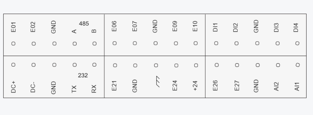
| Terminal | Description |
| E01 | Not used |
| E02 | Not used |
| GND | Signal ground |
| 485 A | RS-485, 120 ohm termination resistor, A |
| 485 B | RS-485, 120 ohm termination resistor, B |
| E06 | Digital output 1 |
| E07 | Digital output 2 |
| GND | Signal ground |
| E09 | Not used |
| E10 | Not used |
| DI1 | Digital input 1, Pull up input |
| DI2 | Digital input 2, Pull up input |
| GND | Signal ground |
| DI3 | Digital Input 3, Pull up input |
| DI4 | Digital Input 4, Pull up input |
| DC+ | Input power, +24 VDC |
| DC- | Input power, ground (earth) |
| GND | Signal ground |
| 232 TX | RS-232, Tx, RTU Rx |
| 232 RX | RS-232, Rx, RTU Tx |
| E21 | Not used |
| GND | Signal ground |
 |
Signal ground (chassis ground) |
| E24 | Not used |
| +24 | +24 VDC supply, maximum 50 mA |
| E26 | Not used |
| E27 | Not used |
| GND | Signal ground |
| AI2 | Analog input 2, 4-20 mA |
| AI1 | Analog input 1, 4-20 mA |
| Terminal | Unit terminal |
| 232 RX | RTU Tx |
| 232 Tx | RTU Rx |
| GND | Ground (earth) |
| Terminal | Unit terminal |
| 485 A | A |
| 485 B | B |
| GND | Ground (earth) |
Special Device Connection
WARNING: Electrical Hazard
Risk of electrical shock or burn. A certified electrician must supervise all electrical work.
Comply with all local codes and regulations.
The following devices need a special connection to the gateway.
- Cut one end of the VGA cable.
- Connect the cut end of the VGA cable to the gateway according to the information below:
| CCD Terminal | Connector pin |
| Tx | 2 |
| Rx | 3 |
| GND | 5 |
| CTS/RTS | 7/8 connected together |