
Connectivity Questions
General Connectivity Questions
- Go to Stations.
- Select a station.
- Go to Settings.
- Go to the tab Connectivity.
- Click Replace.
- Type the serial number of the gateway.
- Click Replace.
Avensor replaces the gateway.
- Go to Stations.
- Select a station.
- Go to Settings.
- Go to the tab Connectivity.
- Click Delete.
Avensor deletes the gateway.
The user roles Customer administrator (CA) and Service personnel (SP) can restart a gateway.
In normal conditions, a gateway restart is not necessary.
- Go to Stations.
- Select a station.
- Go to Settings.
- Go to the Connectivity tab.
- Click the Restart button.
The gateway restarts.
This information is applicable to the CCD 401 gateway.
- Go to Stations.
- Select a station.
- Go to Settings.
- Go to the Connectivity tab.
- Click Edit.
- Type the IP address in dot-decimal notation. Examples: 10.10.10.2, 192.168.200.14
- Select the netmask.
- Click Confirm.
Avensor updates the IP address settings.
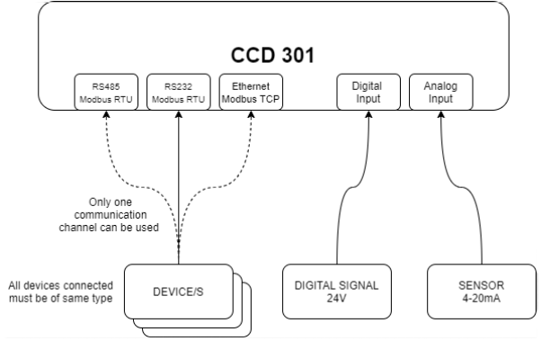
Yes, a rain sensor can be connected with the following connectivity types:
- Digital input
- Analog input
- Modbus communication
No, Modbus-connected devices must be of the same type.
It is possible to add devices that are connected directly to the gateway. That is, analog input and digital input/output.
Note that Modbus-connected devices must use the same connection type. For information on connection types and limits in number of devices, see Compatible Devices.
The voltage requirement differs between the CCD and the digital I/O:
- The CCD runs at 12-16 VDC.
- The digital I/O runs at 24 V.
Thus, at a low voltage, the CCD can communicate with its devices but does not have sufficient power to overcome the relay of the digital I/O.
To use the digital I/O, make sure that the power supply for the CCD is 24 V.
Below RS232/RS485 communication parameters supported:
- Baudrate: 9600, 14400, 19200, 38400, 57600, 115200
- Databits: 7, 8
- Stopbits: 1, 2
- Parity: NONE, EVEN, ODD
- Modbus : 1-247
Information about the maximum number of devices can be found on the Compatible Devices page.
CCD 401
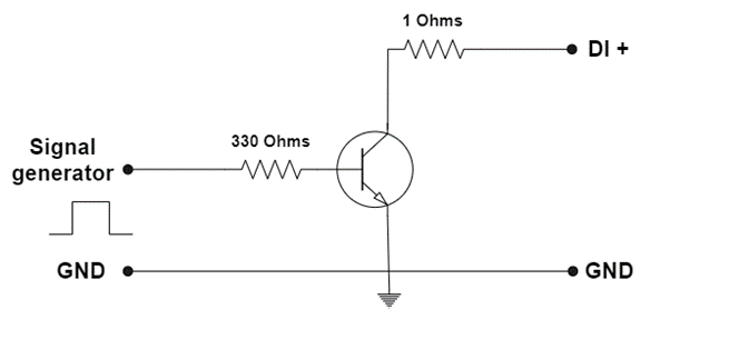
For CCD 401, digital input is active when connected to GND and it is inactive when open.
It indicates that the modem is not responding appropriately to Avensor's attempts to communicate with it. Please view the matching Error messages FAQ for additional details.
It is recommended to use the suggested antenna. It is possible to use another antenna under the following conditions:
- The antenna does not affect the radio frequency (RF) properties.
- The antenna is the same antenna type as the recommended antenna.
- The antenna has the same or lower gain than the recommended antenna.
- The antenna has the same RF characteristics as the recommended antenna.
Yes, the CCD 401 gateway has an internal lithium-ion battery with one cell, 2600 mAh.
The CCD 401 gateway supports four digital inputs. Each digital input can be used either as a normal input or as a pulse counter. The digital inputs have an internal pull-up resistor.
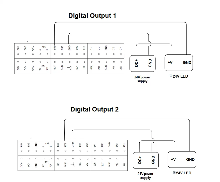
The CCD 401 gateway supports two digital outputs.
For more information about the terminals, see How do I connect the digital outputs on CCD 401?
For more information about the maximum load, see What is the maximum voltage that can be applied to a digital output?
The following connection charts show how to connect the digital outputs on CCD 401.
CCD does not have a SIM card in the slot, it has a built-in eSIM. When the CCD connects to the power, the eSIM connects to the roaming partners countrywide. The user can insert a 3FF micro-SIM card in the SIM card slot. The 3FF micro-SIM card overrides the built-in eSIM.
Yes, but this will make digital input and digital output non-functional. Use this way only if your setup does not require them.
Before adding CCD 401 in Avensor, examine the following:
- The device is turned on and the network LED is solid or blinking green.
- Cloud connection LED is solid or blinking yellow.
The IP/subnet mask for CCD 401 is 10.10.10.2/255.255.255.0
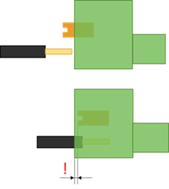
The terminal block is designed for stranded and solid wires with an area between 24 and 16 AWG (0, 205 – 1, 31 mm2). Stranded cable shall be striped 7 mm and twined for mounting. The orange spring button must be pressed to bottom before inserting the cable in the terminal blocks. The spring button shall be pressed behind the front surface of the terminal. For this, a tool with a small tip must be used.
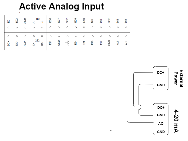
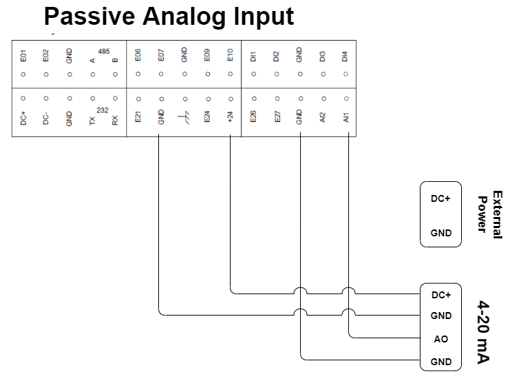
Yes, it is possible. Look at below diagram to understand the connection requirements:
These requirements apply for the antenna installation:
- The antenna must be kept away from the radio or EMC source.
- The antenna cables must be kept away from other electronics.
- The length of the antenna cables must be as short as possible.
- The antenna cables can run the full length but they must not be bent to avoid interference and crosstalk.
The signal strength and device status can be viewed in the Avensor application.
Antenna:
- SMA connector
- Maximum 4 m (13.1 ft) cable
- Torque 0.56 Nm (0.41 lb.ft)
Check the network signal strength.
| LED | State | Description |
| Solid green | Excellent or good signal strength | |
| Solid red | Medium or fair signal strength | |
| Unlit | Poor or no signal |
The state of LED must be solid green to avoid the connectivity problems.
| LED | State | Connection |
 |
Blink or solid yellow | Yes |
| Unlit | No |
The connection procedure takes maximum 15 minutes.
The unit must not be disconnected during the connection procedure.
The recommended mode of communication for CCD 401 is cellular connectivity. The unit can also communicate through Ethernet. When the Ethernet connection is used for the internet, cellular connectivity is not available.
Check that the firewall settings allow traffic on these ports for the selected network:
- MQTT 1883 and 8883
- HTTPS 443
Do the following to connect the unit to the Ethernet:
- Turn off the unit.
- Connect the Ethernet cable to the RJ45port of the unit.
- Turn on the unit and wait up to five minutes for the connection to set up.
Digital inputs/outputs and analog inputs
- Go to Stations.
- Select the station.
- Go to Devices.
- Click the button Add device.
- Select the device type Digital input.
- Do the following steps for each port:
a) Type the name of the data point.
b) Set the option Mode to Enabled.
c) Define the data point.
d) If an alarm is connected to the data point, then configure the alarm settings in the tab Alarm mode.
The tab is only visible for some configurations of the data point.
e) If applicable, configure the unit and scaling of the input value in the tab Unit and scaling.
The tab is only visible for some configurations of the data point.
f) Click the Save button. - Click the Add device button.
Avensor installs the device.
The pulse-counting mode counts up to 12 counts each minute. The supported pulse width is 200 ms. The counter has a maximum 16–bit unsigned value. If the counter reaches the maximum value, it automatically resets to zero.
This function is available when the Remote control service is enabled for the related station.
- Go to Stations.
- Select a station.
- Go to Live data.
- Click the settings icon for the digital output device.
- Select the status of the digital output device.
See Remote Access FAQs for more information.
Prerequisites:
- The gateway in usage is CCD 401.
- The Remote Control functionality is enabled for the customer.
- Go to Stations.
- Select the station.
- Go to Devices.
- Click the Add device button.
- Select the device type Digital output.
- Type the number of the digital output port on the gateway that the device is connected to.
- Select the initial status of the digital output.
- Click the Save button.
The CCD 401 gateway supports two digital outputs. The gateway supports a maximum voltage range of 24 V. The outputs are open collector outputs.
The output device that the digital output controls, for example a relay, must connect to an external power supply and to the digital output.
The outputs have an internal 33 kiloohm pull-up resistor to 24 V. The maximum sink current of the outputs is 100 mA.
| Input Voltage | Description |
| 24 V | Maximum voltage |
| Over 15 V | Low level |
| Under 5.5 V | High level |

- Go to Stations.
- Select a station.
- Go to Devices.
- Select the device that has a digital input.
- Go to the tab Ports configuration.
- For the applicable port, click Edit.
- Edit the field Name.
- Click Save.
- Go to Stations.
- Select a station.
- Go to Devices.
- Select an analog input device.
- Go to the Data point thresholds tab.
- Click the Add data point button.
- Fill in the fields.
- Click Save.
Avensor adds the data point to Live data.
Modbus
| Gateway | IP address range | Recommended IP address |
Maximum number of connected devices |
| CCD 401 | 10.10.10.1–10.10.10.255 | 10.10.10.10 | 4 The devices must be of the same type. |
Most devices use port 502, which is the standard port for Modbus TCP.
The Modbus server address must be defined for the device to communicate with the gateway and Avensor through Modbus TCP. If the device does not have a Modbus server address, it is possible to use 1 as the address.
If the IP address in the device is changed, the device can need a restart before the change applies.
The CCD 401 does not have a Modbus address. The Avensor application contains a field to enter a slave address for the devices which uses both an IP address and a slave address as identifiers.
Connectivity issues
It means that the device is not communicating with the CCD. The communication cable might not be installed correctly, or the settings in the application or the device is not correct (wrong Modbus address or other communication link parameters).
Please see the Alarms FAQs for more information.