
Sustainable oxidation ditch design
Abstract
Accounting for a large part of today’s biological wastewater treatment processes worldwide, the various executions of the oxidation ditch remain popular even for green field projects. Process requirements and space limitations push the boundaries of the capacity of the oxidation ditch to the point where detailed 3-dimensional design must be considered already at the concept stage. The 0-dimensional approach may result in practically unfeasible systems. Some parameters to help understand and alleviate the issue are given, referring to the characteristics of mechanical equipment for aeration and mixing. Standardized design methods should include a number of these considerations.
Biological wastewater loop reactors
Closed loop activated sludge reactors for wastewater treatment, usually called oxidation ditch, have evolved for decades. Whereas historically mechanical surface aerators were used, footprint restriction and energy efficiency have called for a move to deeper reactors commonly equipped with bottom mounted diffused aeration systems, relying on submerged propeller mixers to drive the circulation, Fig. 1. The blend of plug flow character for fast processes and complete mix character for slow processes invites a number of innovations, for instance inclusion of anoxic (for denitrification) and anaerobic (for biological phosphorous removal) zones, while often retaining robustness and low surplus sludge yields. Some ditches are designed for intermittent aeration, and some ditches are required to avoid anoxic conditions throughout.
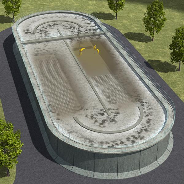
Figure 1. Oxidation ditch with bottom diffused aeration and submersible mixers.
Basic hydraulic guidelines
A sanity check, and ideally a high quality CFD simulation, should be made at an early stage to ensure that there is physical space for the aeration and mixing equipment, while observing clearances between these, and between them and other tank internals or ditch bends and guide vanes, Fig. 2. These clearances fall in two categories. The first type must ensure that the energies released by the equipment, or any inflows to the tank, do not cause excessive stress on any installed parts. The second type must ensure that the efficiency and effectiveness of each component remain maximized. A potential third type is the reservation of a deox zone inside the reactor, approaching the outlet.
![]()
Figure 2. Some standard minimum clearances to observe in wastewater loop reactors [1].
Among the first, primary or secondary mixed liquor flows generated by mixers or the plumes from the aerators must not jeopardize any installed part. But flow skewness introduced by inlets, turns, vanes and other parts are also a threat. It must be remembered that operation 24/7 for many years must be secured. Air bubbles entrained by mixer propellers will cause load variation that is likely to reduce the life of a normal mixer installation by a large factor.
Among the second type, proximity of mixers to a downstream ditch bend or any obstructing part will cost a disproportionate amount of the momentum required to drive the circulation required for suspension, inflow blending, and the aeration efficiency enhancement referred to as the horizontal flow effect. Less obvious, but no less important, is the impact of obstructing parts, including guide vanes, in the way of the aeration plume as it extends downstream along the liquid surface. Recovering the energy of the air buoyancy is tantamount for total energy efficiency, and sometimes even further installations are motivated to this effect.
While these clearances can usually be expressed in terms of one to a few times the water depth, Fig. 2, they can be affected by the detailed reactor and installation layout and by the energies engaged in aeration and mixing. For instance, large air flows combined with channel widths considerably greater than the depth, or other hydraulic stoppers, are likely to cause recirculation flows that cause undue stress on installed parts. Recirculation flows directed to the surface by plumes or channel narrowness may cause unwanted accumulation of floating scum, etc.
On top of these clearances, the locations of instruments used for process montoring and control should be carefully considered in their relation to inlets, aeration zones, loop directions and local flow character, avoiding for instance recirculation eddies and high stress regions.
The interdependence of aeration and mixing design must be observed. Aeration causes loop flow momentum losses that can be severe, and the mixer powered loop circulation increases the oxygen transfer efficiency (the Horizontal Flow Effect, HFE). Accommodating for sufficient mixers to thus permit a reduction of the aeration blower capacity can often permit a substantial reduction of both capital and energy cost. This philosophy is also in line with the mitigation of consequences of some design pressures commonly seen today.
Design pressures
Legacy structure such as tank internals or constrictions can be a cause of concern as their effect on the loop flow can increase undesired stress on equipment. On the other hand, for green field projects the pressure on footprint results in a shift toward greater water depth. Similarly, water temperatures greater than 10 or 20 oC on many locations promise faster reaction kinetics allowing the tank dimensions to be sized for shorter retention times than in the colder water regions. The consequences of greater depth and faster reactions are usually expected to be an increase in capital and energy efficiency.
It is instructive to consider the total blower power spent on a reactor divided by its total mixer power. While motor, transmission and impeller efficiencies can blur this picture slightly, it is remarkable that this power ratio is often in the range 5 – 15, yet the mixers are required to govern the overall flow against the bubble plumes! Larger ratios occur, and at the high ratio end stricter layout guidelines are required to ensure the correct flow and oxygen transfer rate regime, if even possible.
A hydraulic alternative to the power ratio is the Froude number defined as twice the desired mixed liquor kinetic energy flux through a ditch cross section divided by the displacement power of the bubbles entering the tank near the bottom, elevating the liquid surface. Again depending on the total civil and equipment layout, this ratio may need to exceed some limit in the range 0.2 – 0.4 to ensure correct operation.
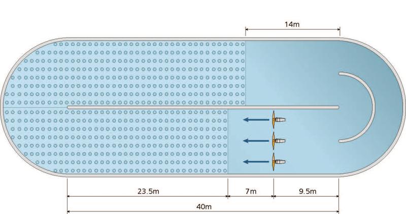
Figure 3. One of several strategies for the use of floor space when equipment crowding occurs [1].
While civil structure should preferably be designed to avoid equipment crowding, excessive stress and energy-demanding balancing of the aeration-mixing system, it is commonly the case that it is rather subject to other considerations. The combined aeration and mixing system must then be tweaked using extraordinary or even sub-optimum designs, Fig. 3. Stretching the well-known and tested designs requires detailed 3D considerations at an early stage, to ensure that proven high efficiency solutions can be fitted to the civil framework. This certainly includes the balanced layout of the aeration system and the mixing system that drives the circulatory flow, whether the reactor is intended for only oxygen transfer, or for other simultaneous duties as mentioned above.
Recommendation: Accurate CFD simulation
Computational Fluid Dynamics (CFD) is a suitable tool for understanding the functioning of a design in sufficient detail to detect and help avoid the risks discussed above. CFD simulations are mostly carried out with a commercially available general purpose software (or even a free software), but requires meticulous care by the CFD engineer and those supplying the underlying information, from input to simulation to interpretation of the output.
Domain specific inputs include the selection of models and computational methods for a given simulation, that must be proven for oxidation ditches in general. This includes selecting fluid dynamics models and numerical methods, and a proven spatial discretization (meshing) method. They can also include e.g. properties of liquids (water, mixed liquor, return sludge, …) and gases (e.g. air) unless specified for a project.
Project specific inputs include accurate geometric information that permits to build a 3D digital copy of the tank and systems inside. The importance of geometric accuracy is illustrated in Fig. 4. Operating conditions, such as flow rates through gas and liquid inlets, mixer speed or thrust and torque etc, must also be specified with care. Specific material properties can also be defined for a given project.
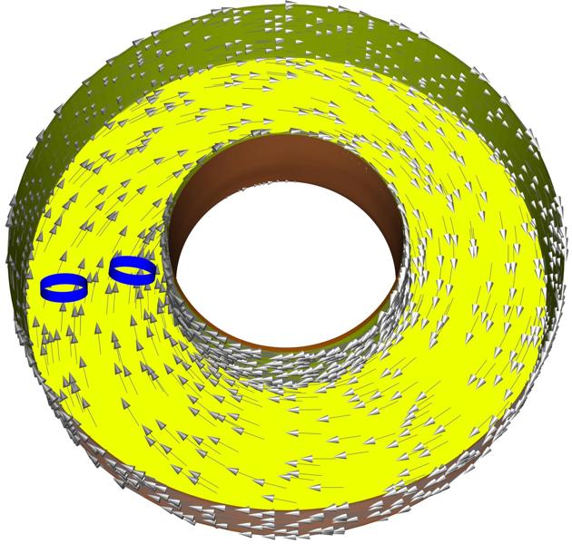

Figure 4. CFD: Impact on iso-velocity surfaces of seven 100 mm ´ 100 mm aeration guide rails in a 28 m diameter tank [1].
Typical output from an oxidation ditch simulation are loop velocity and transit times, Fig. 5, blending of streams, solids suspension, Fig. 6, indications of harmful stress or air entrainment into mixer propellers, and oxygen transfer rate. Comparing the oxygen transfer rate with that of a similar aeration system in a square tank gives a quantitative idea of the HFE. Potentially reducing the 3D system to a 1D system [2] can enable fast process simulations using commercially available process modeling tools.
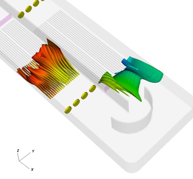
Figure 5. CFD: Mean water age increasing by the transit time 200 s between air plumes.

Figure 6. CFD: Sludge deposit risk at most in the deep blue areas, but transient (time-changing) effects can further reduce the risk.
Further proof of performance
Although CFD simulation and shop-test performance data combine to a comprehensive performance statement, there is sometimes a requirement for onsite performance testing of the aeration system (rate or efficiency of oxygen transfer, energy efficiency), and of the mixers (bulk flow/loop velocity, energy efficiency). There are important differences between different aeration test standards to be aware of, and apart from Xylem’s recommendations [1], there is no bulk flow velocity test standard for wastewater treatment tanks.
A word of caution is in place when testing the oxygen transfer performance by a clean water test. Unless the aeration covers a major part of the tank, or the oxygen transfer rate is very slow in relation to the circulation time, current test standards tend to underestimate the oxygen transfer rate by 5 – 20 %, driving excess capacity and increased cost [3]. Recent developments point to amendments to these standards to better capture the true performance of oxidation ditches.
Acknowledgements
This white paper is based on Uby, Sustainable oxidation ditch design, a presentation given at the Digital World Water Congress, Copenhagen in 2021.
CFD simulations were made by Kalle Pettersson, Alex Loubenets and Antonios Monokrousos, Xylem.
References
[1] Uby, L. 2012 Handbook of Mixing for Wastewater and Similar Applications. Xylem, Sundbyberg.
[2] Alex, J., Kolisch, G., Krause, K., 2002. Model structure identification for wastewater treatment simulation based on computational fluid dynamics. Wat. Sci. Tech. 145, 325-334. https://doi.org/10.2166/wst.2002.0616
[3] Uby, L., 2019. Next steps in clean water oxygen transfer testing – A critical review of current standards. Wat. Res. 157, 415-434. https://doi.org/10.1016/j.watres.2019.03.063